Monday, January 18, 2010
Street Lamp - Modeling and Wrapping the Stem
| Some valuable advice to learn how to obtain a rotational solid and wrap a picture around it using the Projected property |
|

You can also watch a video of this tutorial on YouTube (2' 45")
The entire process consists in seven step and will consuming from 10 minutes to more than one hour, depending on the level of your knowledges. If you've never dealt with these topics, I strongly suggest you read this tutorial: now spending half hour, you will in future save many hours/days of work and obtain more satisfactory results.
The illustration below shows, in a nutshell, the content on this tutorial. From an image of a street lamp, we will draw half profile of the stem and use it to generate - through rotation - the 3D stem of the lamp. To paint the stem, we will simply define as Projected the starting image, select all its elements and apply to them this texture with a single clicking using the Bucket tool.
THE SEVEN STEPS
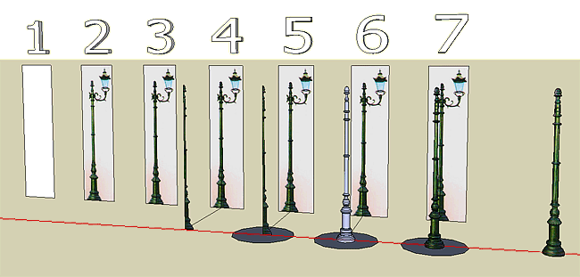
STEP 1 - Draw rectangle (VERY EASY)
Draw a rectangle with the basis parallel to x/red axis and the height parallel to the z/blue axis
STEP 2 - Import the image (EASY)
Import as texture the image of the Street Lamp - of course in this step you will give the rectangle the right size for your model!
STEP 3 - Draw the emi-profile (MAY BE DIFFICULT)
This step is not too difficult but it's crucial for the quality of the final result!
You have to draw exactly the right (or, if you prefer, the left) half of the profile of the lamp stem. Use the Line command.
To avoid the lines go outside the rectangle (it can happen!), I advise you to adopt this precaution:
- click WITH SINGLE CLICK over the face of the rectangle in order to selecting its surface (caution: don't click with double click!)
- now click with the right-button in order to obtain the context menu for the face
- from this menu choose Align View
- right-click again on the face as in 2
- now choose the Zoom Extent command
I realize that at first glance this seems a bit complicated, but I assure you that once applied, you will not forget this most useful procedure and you will use it very often!
NOTE - The contour of emi-profile must be a closed line, wich must delimit a single area (unless this happens, you can not go to next step).
STEP 4 - Bring out the emi-profile (A BIT MORE DIFFICULT...)
The crux of this step cosistes of extracting the emi-profilo copying it to a location just exactly perpendicular to the extraction point! Note that even a small difference could lead a result wich does not correspond to our expectations!
In order to obtain this result, I advise you to adopt this precaution:
- draw a segment from the central lower point of the lamp in the y/green direction (exactly perpendicular to the rectangle)
- click (or even double-click) over the face of the emi-profilo in order to select this face
- now choose the Move/Copy tool: the cursor will take the form of a cross with the tips
=> in this way SketchUp tells you that it is preparing to make the Move of the selected surface
- without clicking at any point, press the Control key: near the cross of the cursor will now appear a little + (plus)
=> in this way SkethUp tells you that it is preparing to make a Copy of the selected surface - now you can perform the Copy itself, and so Copy the emi-profile at the end of the line previously drawed
In this step you must draw a regular polygon using the Circle tool. Therefore you must click on Circle tool - the cursor will take a form of a lapis with a little circle around its tip.
Now we should observe these basic facts:
- the little circle change its color depending on where you position the cursor: this color shows you in what plan SketchUp will draw your poligon! for instance, if the color is RED, then SketchUp will draw your polygon in a plan perpendicular to x/red axis, if GREEN to y/green axis, if BLUE to z/blue axis and if it is BLACK the SketchUp will draw your polygon in a plan oblique than the main planes
- if you look in the low right corner of the SketchUp workspace, you can see a number (probably the number 24): this number indicates how many sides will have the polygon you will draw with the next Circle operation!
NOTABLE! the low right corner of the SketchUp workspace is reserved to manage the Value Control Block (VCB), a command system through wich we can provide some interesting commands and parameters to SketchUp!
Now if you type another number, for instace 12 (clicking on key 1 and then on key 2) and then press Enter key to confirm your input, this value (12) will appear in the VCB (Value Control Block) and you are sure that the next polygon will have 12 sides! you can also retype or correct the value in VCB as long as you not draw the polygon or not abandon the Circle comand
STEP 6 - Generate the 3D lamp stem (MUCH EASIER THAN YOU THOUGHT...!)
The procedure to be used is very simple:
- first select the polygon, clicking with a single click over its surface: the surface will be selected
=> we can name this polygon THE LEADER FIGURE, id est the figure that determines the movement
- click on the Follow Me tool: the cursor will take the form of... Follow Me!
- now simply click (single-click) on any point of the emi-profile obtained in Step 5
=> we can name this figure THE TAKEN AROUND FIGURE, id est the figure that The Leader Figure takes around to generate our unbelievable result!
A little spell...! If this gives you a great satisfaction, this means that the modeling is for you...
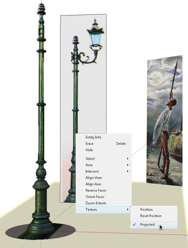
STEP 7 - Paint the stem - (NOT DIFFICULT AND SIMPLY... MAGIC!)
Even in this case the procedure to be used is almost simple:
- Define the SOURCE FACE as Projected
You must right-click over the emi-profile, choose the last row, Texture, and set the sub-voice Projected so that it is flagged (note that this voice functions as a switch)
See the big picture at the beginning of this tutorial! - Select the TARGET FACES (id est all the elements of the lamp)
The simpler way to obtain this is (1) erasing the segment between the rectangle and the polygon and (2) triple-clicking on any point of the polygon (or the lamp): the triple-click is very powerful, and causes the selection of all items connencted to the triple-clicked segment/face
- Correctly set the PAINT tool to the SOURCE TEXTURE
This point is crucial but it's easy to do:
- First you must click on the PAINT tool: the cursor will take the form of a Bucket
- Then you must press the Alt key and hold it pressed: the cursor will take the form of a Dropper,
- Lastly you must click over the SOURCE FACE (id est the emi-profile) - And now... PAINT all the TARGET FACES in A Single Shot!
Now you must release the Alt key - so the cursor from a Dropper returns a Bucket. With this Bucket you can simply click on any point of the selected stem... a magically paint the whole stem in a single shot!
As you can see yourself doing various tests and trials, the projection is always exactly perpendicular to the figure defined as Projected, and the result is just what we can obtain projecting a luminous image over solid objects.
And that's it! Please notify me any typos or not clear topics and send me your comments using the COMMENTI/COMMENTS link at the bottom of this page!
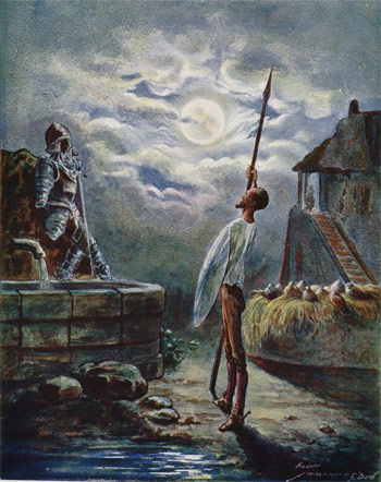 Arrimado á su lanza ponía los ojos en las armas...
Paul Gustave Louis Christophe Doré
watercolored by A. Audet
1905-Barcelona-Tasso-01-014
(see Greetings)
.

Labels: -Street_Lamp_Stem
Saturday, January 16, 2010
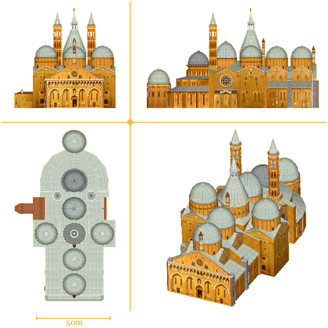
Orthogonal Views - Saint Anthony
Labels: .ORTHO
Thursday, January 7, 2010
Cross Shadows
| There are many ways to make the shadow of a cross... Here I show the five most common. |
|
Churches are my passion, and I don't miss the opportunity to carefully examine all those that are published in 3DWarehouse - often there are beautiful! But sometimes, watching the shadows of the crosses, we can find some surprise!
To make the crosses atop churches we usally use *. png files with the big advantage that with a single image we can achieve a great realistic effect because of the transparency of png files - but be careful: sometimes the shade is an absurd rectangle, ugly looking and... very unrealistic
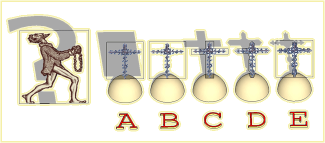
Below are briefly presented the 5 most common strategies, highlighting the advantages and disadvantages of each method.
A) DOING NOTHING
This strategy is very time saving... but the result is ever very ugly. The only thing you can do is turning off the shadows in your model (in View>Shadows turn the switch to OFF, or in Window>Shadows panel turn the switch Display Shadows to OFF).
Do not use - or use only if the model does not include the shadows
B) REMOVING SHADOW
This strategy is very quick to make: you must only right-click over the Cross face and choose Entity Info and thrn to OFF the Cast Shadows switch.
Do not use - or use only if the crosses are very small compared to the rest of the model, and thus their absence may not be noticed
C) BUILDING A SIMPLE OUTER CONTOUR
This strategy can be enough quickly, but may too fatten the shape of the cross!
It may be advisable if the crosses are very small compared to the rest of the model
D) BUILDING A MORE DETAILED OUTER CONTOUR
This strategy can consume more time, but the result may be more captivating. The disadvantage is that the shadow can be much larger than the cross.
It may be advisable when the shape of the shadow should show some details that you deem important
E) BUILDING A LESS OR MORE DETAILED INNER/OUTER CONTOUR
This strategy is the winning strategy! You can trace the outline of the shadow as you feel better, that is, with any level of detail and without any respect to the real contour of the cross. Once you've drawn the outline of the shadow, you must mark all outer surfaces as NOT CASTING SHADOWS (turning to OFF their switches in Entity Info panel)
The winning strategy!

from Don Quixote's love penance in Sierra Morena
1947-Paris-Latines-01-054 (see Greetings)
Labels: -Cross_Shadows
Wednesday, January 6, 2010
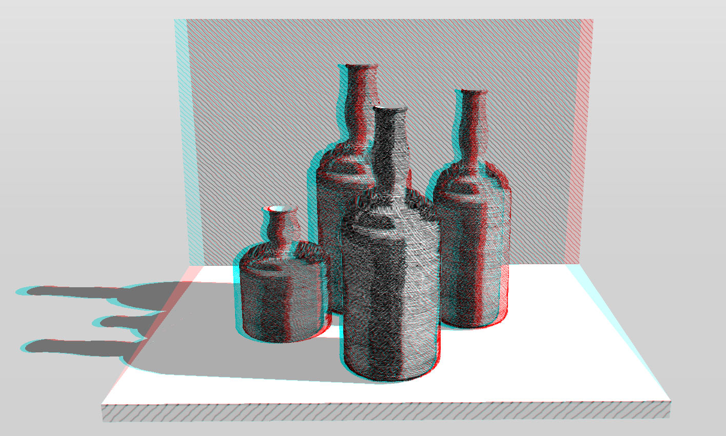
Homage to Morandi
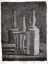 A stereo view of my model Homage to Giorgio Morandi
Morandi was one of the most impressive Italian painters of his day. Throughout his career, he concentrated almost exclusively on still lifes and landscapes, except for a few self-portraits. With great sensitivity to tone, color, and compositional balance, he would depict the same familiar bottles and vases again and again in paintings notable for their simplicity of execution.
Morandi executed 133 etchings, a significant body of work in its own right, and his drawings and watercolors often approach abstraction in their economy of means. He explained: What interests me most is expressing what’s in nature, in the visible world, that is; he also said, Nothing is more abstract than reality.
[EXTRACTED FROM WIKIPEDIA]
*
.
Labels: +3D, +3D_Morandi
Monday, January 4, 2010
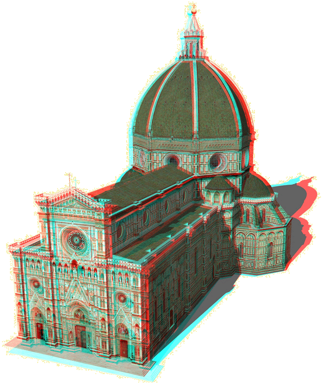
Florence Duomo
Labels: +3D, +3D_FlorenceDuomo
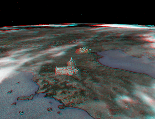
View of northern Italy
A view of the north Italy, with my models of the Duomo of Florence and the Basilica of Saint Anthony in Padua
Labels: +3D, +3D_PaduaFlorence
Sunday, January 3, 2010
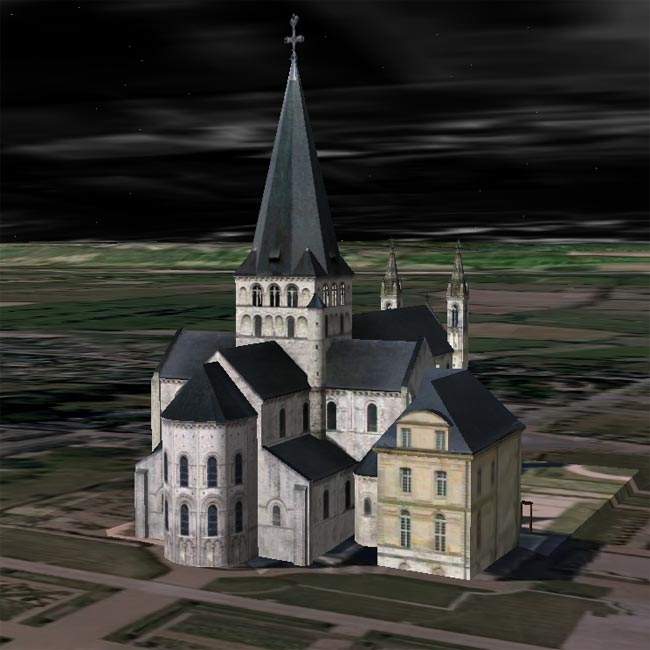
Saint-Georges de Boscherville in the round
An image of my model of Saint-Georges de Boscherville (published at Trimble 3D Warehouse)
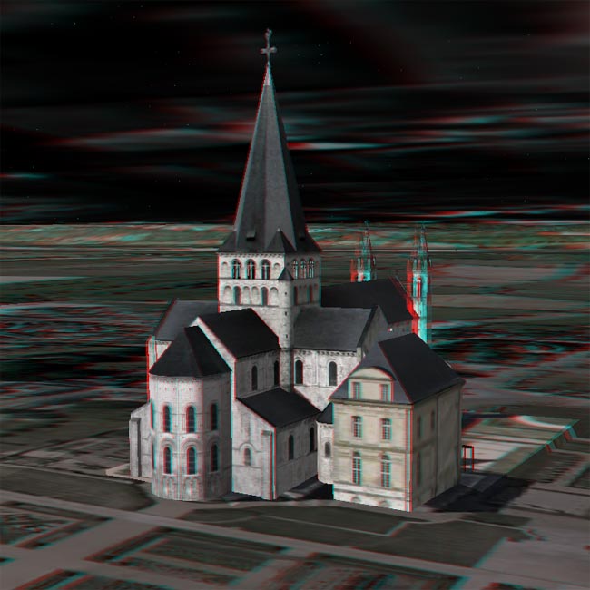
The same image in stereoscopic version (use stereo glasses to see the image in 3 dimensions - remember: red for the left eye, blue for right)
.
Labels: +3D, +3D_Boscherville
Friday, January 1, 2010
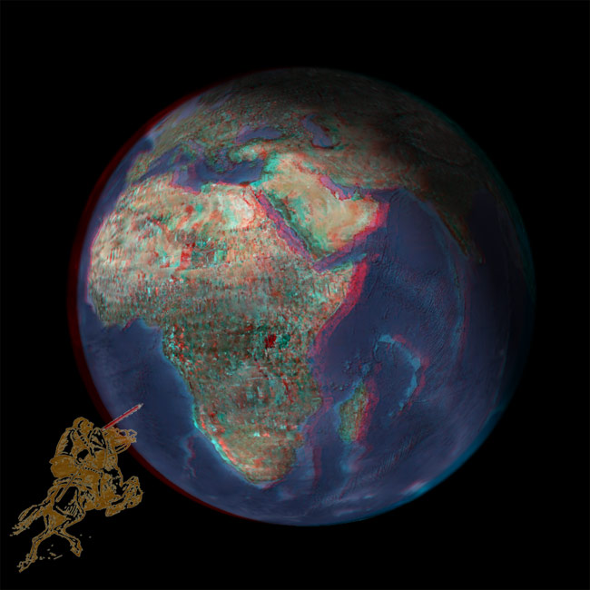
Google Earth, Our World
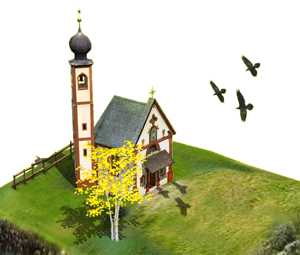
St. Johann with a flight of crows in the round
An image of my model of St. Johann with a flight of crows (published at Trimble 3D Warehouse)
*
The same image in stereoscopic version (use stereo glasses to see the image in 3 dimensions - remember: red for the left eye, blue for right)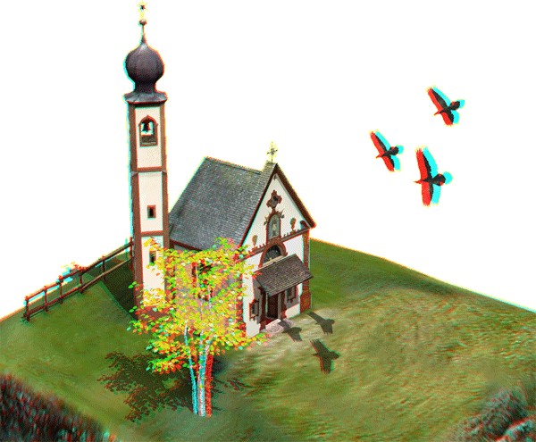
.
Labels: +3D, +3D_Funes, +3DStereo_Funes
![]()
