Saturday, October 16, 2010
The design of Bernini's Colonnade
| This article refers to the model of the St. Peter's Basilica and Bernini's Colonnade you can see in 3D warehouse at https://3dwarehouse.sketchup.com/model/30be7ffa11d79288ee7128ac0228a7ac |
If you liked this article, if it has aroused your interest or your criticism, I invite you to leave a comment (at the bottom of this page) - it may be an incentive for me to write more!
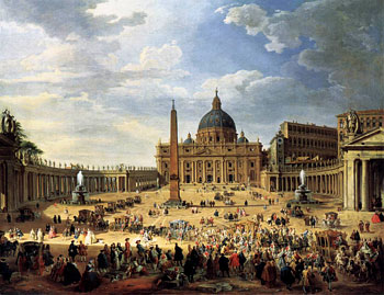 When, a few months ago, I decided to develop a model of St. Peter's Basilica and Square, I set myself the goal of providing a representation with a level of detail, accuracy and texturing that would allow to appreciate the beauty, wealth and the greatness of the original but, at the same time, to minimize the complexity of the technological model in order to make possible its acceptance in the Photorealistic layer of Google Earth.
The main critical points in relation to the complexity are readily identified in the Domes and the Colonnade.
With the Domes I had gained significant previous experience, for example with St. Basil that was initially rejected by Google Earth because as too complex. So I was forced to reduce the number of dome sectors and to remove some 3D details (such as surveys of red diamonds on the red-and-green dome or the relief on the white-and-blue dome) using special techniques of photografic reduction, without compromising the splendor of those forms so colorful and lively. Thus I have provided two different versions of the same model (St. Basil's Cathedral) as you can still see in 3D warehouse at http://sketchup.google.com/3dwarehouse/details?mid=c5fa9fa9f209780aaa261f49f4209a7d
For the Colonnade of Bernini, the problem was very different, and for several reasons:
 A) THE STRUCTURE OF COLONNADE
The Colonnade has a very articulated and rounded structure: if we were to implement it using a few sides, we could make the ring shape too edgy! Complex is also the layout of the plinths (colomns and pillars) since it is designed according to specific functional (engineering) and aesthetic criteria.
B) THE STRUCTURE OF THE COLUMNS
Pillars and columns are very numerous (about four hundred!) and it should be possible to distinguish them from each other. Now it is well understood that (a) the number of pillars and columns should be observed religiously, and therefore can not be reduced to a single unit... and (b) it is not possible reduce the number of faces that describes a column without compromising the readability of the column and the ability to distinguish it from the pillars - for example it does not seem reasonable to make the columns with less than 6 sides!
THE FOCAL POINTS
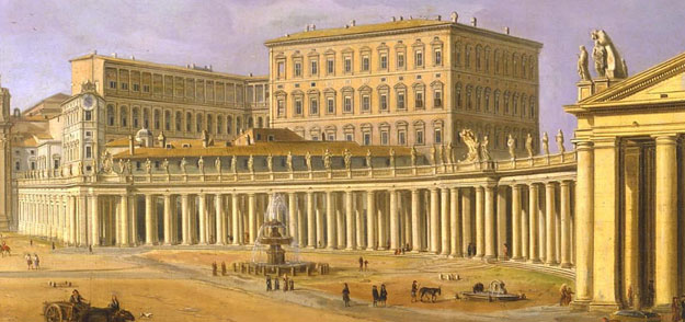
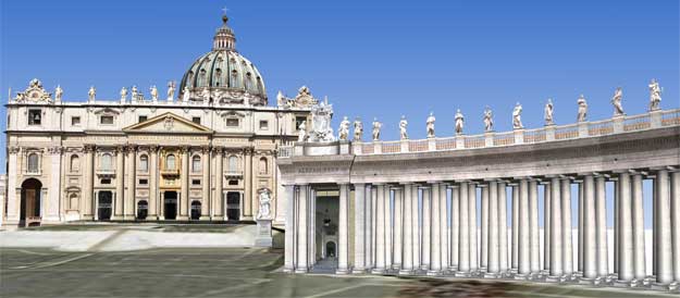
Looking from the Piazza Bernini's Colonnade, the columns of the two arms appear mostly as a powerful "stone wall" that surrounds, embraces and protects the large elliptical space - beyond the wall, however, you can glimpse here and there the openings that allow you to see beyond that wall.
There are, however, across the square, two particular points (also known as "focal points") in which there is a peculiar phenomenon that never fails to arouse feeling and wonder in the viewer: looking at the columns from these points (and only these two points!), the wood of the wall of columns suddenly seems to be very thin, reduceding itself to one simple row of which makes the colonnade almost "transparent".
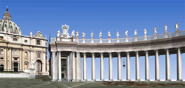
It seems that the Bernini wanted to emphasize with this stylish spectacular fireworks the different values of its splendid colonnade: protect, defend, embrace, and gather the faithful but without confining and oppress... If on the one hand, the main purpose of the colonnade is to protect the people gathered in the square - the "wall of columns" assures them, collects them and protects them from the dangers of the outside world - on the other it is not "oppressive" leaving them free to get in and out, to see also what is "beyond"...
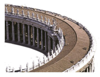
THE STRUCTURE OF COLONNADE
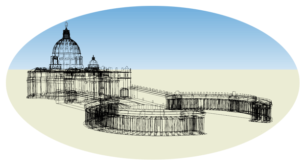
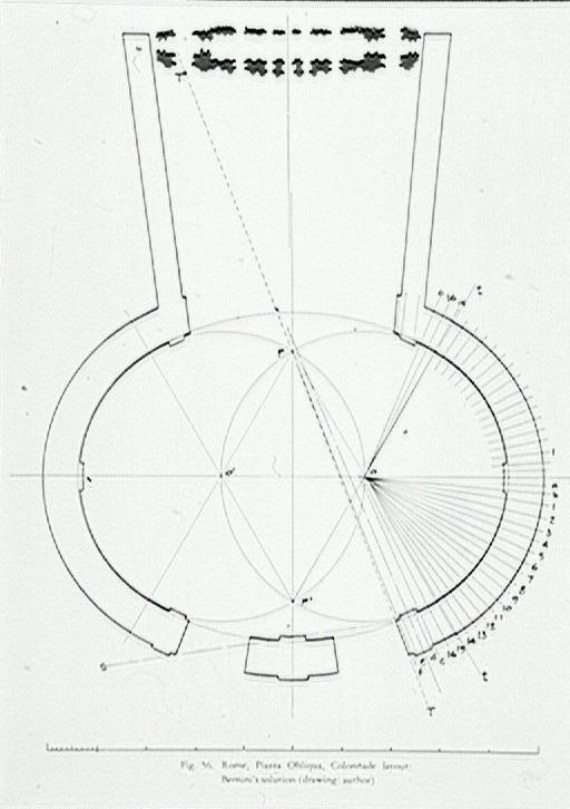 The colonnade is composed of two parts - north and south - symmetrical to the longitudinal axis of the block Basilica+Squares (respectively on the left and right in the picture).
Each part follows a sector of circular crown. The centers of two generator circles are distinct and their distance is exactly equal to the inner radius of the two circular crowns.
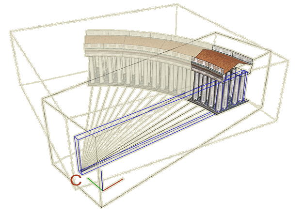
Regarding the column layout, each side has as Generating Element a group of 4 columns arranged radially with respect to that center of the circle; this generating element is repeated at a rate of 3° 45' thus forming three aisles, a central corridor wide enough to permit the passage of a carriage and two narrower side corridors, walkable.
At the two extremes, and the center of each part are the "gates" (Eastern, Central, West) in which the sequence of columns is, more than broken, enriched by the presence of rectangular pillars that alternate columns according to different patterns for each gate (in the West gate, even, the foundations of the pillars and columns are skewed to better follow the inclination of the two "arms" or "branches" which connect the Basilica of the Colonnade).
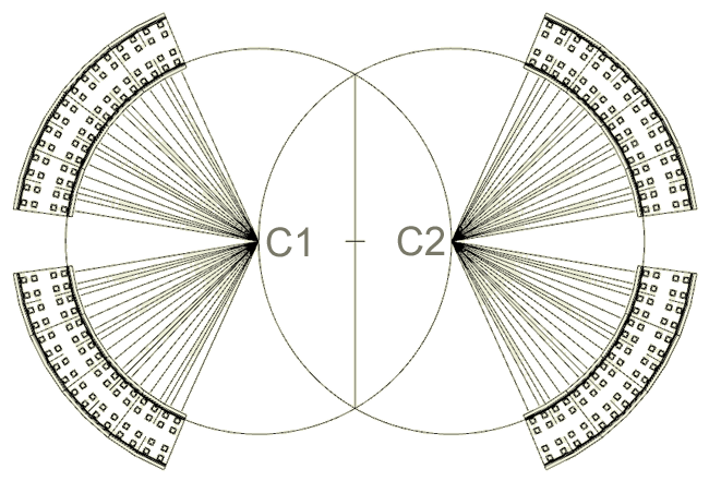
Between each pair of gates is placed a Connecting Sector of 64 columns, id est of 16 Generating Elements previously defined.
The diagrams show how I made the Connecting Sector: the row of four columns (Generating Element) is repeated four times to form a module of 16 columns, and then this form is repeated 4 times.
The Connection Sector thus contains 64 columns and spans exactly (3° 45')*16 = 60 degrees!
In the whole structure of the Bernini's Colonnade, the Connection Sector is repeated four times for a total of 256 columns.
THE STRUCTURE OF THE COLUMNS
From the foregoing considerations, the total number of the columns included in the four Connenction Sectors is exactly 256 - or if you prefer, in binary notation, 1,000,000,000 - a rather interesting number for a Computer Scientist... and a significant number, however, for the Google Earth modeler! Without taking into account that, in the Gates, there are then another thirty columns and nearly a hundred pillars...
Since the complexity of the model depends (also) by the total number of edges and faces, it follows that we must be very careful - and in essence... stingy - in designing the single column: in fact, the number of edges and faces for a single column should be multiplied by 256 - and more - for the whole Colonnade. And then there are the pillars which, being a square section, we worry a bit less, but also contribute to make heavier the model.
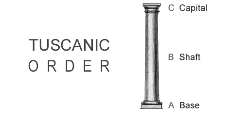
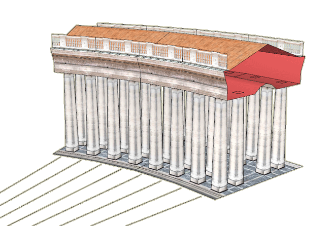
Bearing in mind the type and shape of the columns of Bernini (in Tuscan order, a simplified adaptation by the Romans of the Doric order), and referring to column schematization shown in the figure, I have examined the various possibilities for the design of geometric structures and identified the following scenarios:
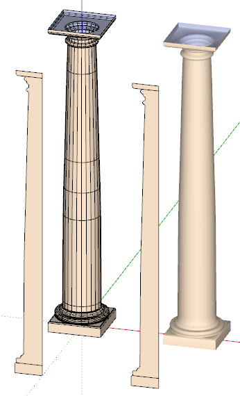 1) WELL DONE COLUMN
 We can design it as follows:
- A: an extrusion of a profile with Am segments along a square (An=4)
- B: an extrusion of a profile with Bm segments with a circle of Bn sides
- C: an extrusion of a profile with Cm segments along a square (Cn=4)
By making some approximations, I think that a column fairly realistic (even when you look at a distance of few meters) could have the following characteristics
A: Profile with Am= 3, Square (with An = 4)
Edges | Faces = [(Am*2+1)*4] | [(An*4)+1]
Edges | Faces = [(3*2+1)*4] | [(4*4)+1] =28|17
B: Profile with Bm=35, Circle (with Bn=24)
Edges | Faces = [(Bm*2+1)*Bn] | [(Bm*Bn)]
Edges | Faces = [(35*2+1)*24] | [(35*24)]=1704|840
C: see A
Edges | Faces = 28|17
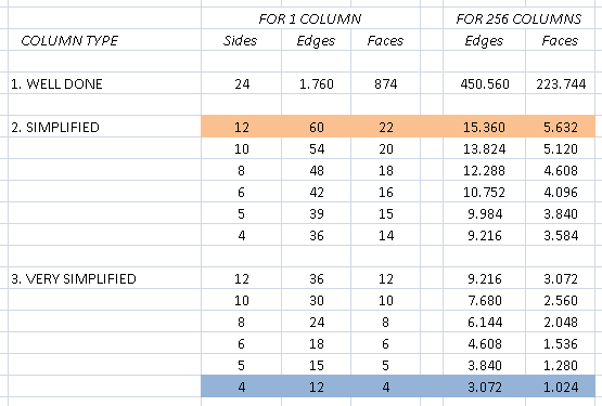
TOTAL FOR COLUMN: Edges | Faces = 1760 | 874
 2) SIMPLIFIED COLUMN
A and B are simplified as parallelepipeds (with 5 faces), while C consists of a simple cylinder or a truncated cone with Bn sides
A: simple parallelepiped
Edges | Faces = 12 | 5
B: Profile with Bm = 1, circle with Bn = 12
Edges | Faces = [(Bm*2+1)*Bn] | [(Bm*Bn)]
Edges | Faces = [3*Bn] | [Bn]
C: simple parallelepiped
Edges / Faces = 12 | 5
TOTAL FOR COLUMN: Edges | Faces = [24+3*Bn]|[10+Bn]
Under these assumptions the overall size depends only on by Bn, the number of sides selected for generating circle.
Some examples:
column to 12 sides: Edges | Faces = 24+36 | 10+12 = 60 | 22
column 6 sides: Edges | Faces = 24+18 | 10+6 = 42 | 16
column 4 sides: Edges | Faces = 24+12 | 10+4 = 36 | 14
3) VERY SIMPLIFIED COLUMN
The maximum of simplification is achieved by giving up the base and the capital, and keeping only the shaft.
The calculation is therefore similar to the previous case
TOTAL FOR COLUMN: Edges | Faces = [3*Bn] | [Bn]
Also in this case the overall size depends only on by Bn, the number of sides selected for generating circle.
Some examples:
column to 12 sides: Edges | Faces = 36 | 12
column 6 sides: Edges | Faces = 18 | 6
column 4 sides: Edges | Faces = 12 | 4
The following table provides a summary of some interesting cases:
It's interesting to note that the three types of columns that are modeled on the classification the classification that I have previously proposed in my article My Method For Classifying 3D Models, namely:
- the VERY SIMPLIFIED column corresponds to G0 = Geometry essential
- the SIMPLIFIED corresponds to G1 - Geometry at first level of detail
- the WELL DONE corresponds to G2 - Geometry at second level of detail
MY CHOICES
I chose two solutions, depending on the destination of the model:
- for the version designed to Google Earth, my choice falls on the column of type 2, Simplified or type 3, Very Simplified with only 4 sides
- for other versions I use the type 1, Well Done less or more refined depending on the constraints (complexity, filesize, etc.)
The choice type 3, Very Simplified might seem too drastic to allow a faithful representation of the column shape, but I think that this solution, in conjunction with an appropriate texturing borrowed from Tromp l'oeil, allow me to emulate both the square base and the rounded column.
Instead of choosing a cylinder, I opt for a truncated cone, to reproduce the tapering of the Tuscanic columns of Bernini.
Finally I smooth all faces using a smoothing angle exceeding 90 degrees: this workaround will cause some shadow effect in some lighting conditions, but has the great advantage of reducing the effect of very sharp edges thus fostering the impression of roundness.
I believe that this choice does have the advantage of being very light in terms of filesize and give a good illusion of roundness especially when looking at the Colonnade at an average distance.
On the other hand it seems appropriate to manage even a version with a greater level of detail, for example, be used for the production of movies or to make the photo shot at close range. In these cases in these cases, I can safely use SIMPLIFIED or even WELL DONE columns.
RECORD-BREAKING COLUMNS
While looking for a light solution for Google Earth, I devised a trick that allows me to get column (it would be more accurate to say a parallepiped...) using an incredibly low number of faces!
The question was:
Does ONE COLUMN require a minimum Edges|Faces = 12|4?
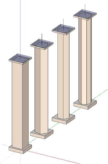
At first glance, a simple column (such as those shown in the figure) requires at least the following geometric elements:
- 6 sides, or only 4 if you give up to the two horizontal faces
- 12 edges necessary to define the 4 (or even the 6) faces
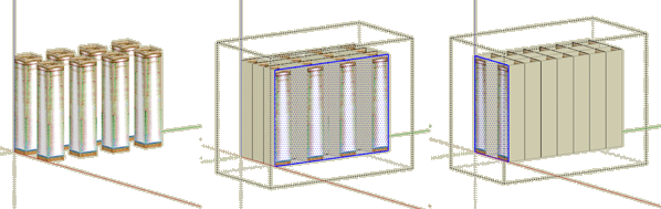
But now consider the above diagram, showing eight columns obtained using a number of textured surfaces with partially transparent png files properly designed: using only 12 faces (4 perpendicular to the axis X and Y axis 8 ) and only 48 edges (four for each side) the illusion is perfect!
Then the response is:
No! In this case ONE COLUMN requires only Edges|Faces = (48/8) | (12/8) = 6|1.5!
that is, less than half of what seemed at first sight.
So, if the Colonnade had more than 1,000 columns, I would certainly have adopted this solution!
If you liked this article, if it has aroused your interest or your criticism, I invite you to leave a comment (at the bottom of this page) - it may be an incentive for me to write more!
.

Labels: .CHURCHES, Berninis_Colonnade
# posted by Arrigo Silva @ 10/16/2010 02:00:00 AM 
Comments:
<< Home

Una teoria molto interessante, quella della semplificazione delle colonne, che salva il risultato estetico finale riducendo al minimo lo spazio occupato dal colonnato. Ottima teoria, ottime idee - come sempre!
Interessante il tutto. Veramente ottima l'idea di creare 2 modelli, di cui uno eseguito con le colonne di tipo 1. Le colonne super semplificate, per quanto siano ben testurizzate sono sempre inferiori a quelle della tipologia 1. Anche perchè la semplificazione è importante, ma fino ad un certo punto: sono d'accordo con te, non si può sacrificare la forma, altrimenti si perde la bellezza dell'architettura.
# posted by  : October 23, 2010 at 4:02 PM
: October 23, 2010 at 4:02 PM
Making 3D models is, in many ways, working with illusion. A great illusionist must do his trick without a struggle. The illusion must appear naturally and without an effort.Too many useless polygons and faces unveil the struggle of the modeller.
Many thanks, Mr. Dalbosco, for showing us your way of eliminating the struggle. The question of too many? The question of too few? The questions that haunts us all.
Regards.
St.Pall
Many thanks, Mr. Dalbosco, for showing us your way of eliminating the struggle. The question of too many? The question of too few? The questions that haunts us all.
Regards.
St.Pall
Really interesting and instructive. An impresive modelling lesson. Thanks for so great work. Regards!
Gracias Enrico por esta impresionante exposición que has hecho de tu buen hacer. Muy didáctico.
Una obra de arte.
Una obra de arte.
Complimenti Enrico per aver approfondito e spiegato dettagliatamente, in maniera chiara e facilmente comprensibile, l'iter della realizzazione del tuo incredibile modello. Penso che sia giusto, cercare di trovare l’ equilibrio fra perfezione e leggerezza nella modellazione . . . non bisogna dimenticare che si tratta comunque di opere architettoniche già perfettamente realizzate nella realtà . . . quindi la bravura del modellatore sta’ soprattutto nel "rendere" tali opere, animandole secondo la propria interpretazione e sensibilità artistica.
# posted by : January 31, 2011 at 5:32 PM
: January 31, 2011 at 5:32 PM
Your method of using the transparent png files is genius. I will definitely use this method in the future and tell others.
Have you ever attempted using 3D immersive goggles to walk through your models? There is a program that converts SketchUp .dae files to 3D immersive files that can be viewed in 3D goggles like the HMZ-T1 goggles.
Have you ever attempted using 3D immersive goggles to walk through your models? There is a program that converts SketchUp .dae files to 3D immersive files that can be viewed in 3D goggles like the HMZ-T1 goggles.
<< Home
![]()

Post a Comment